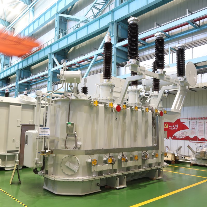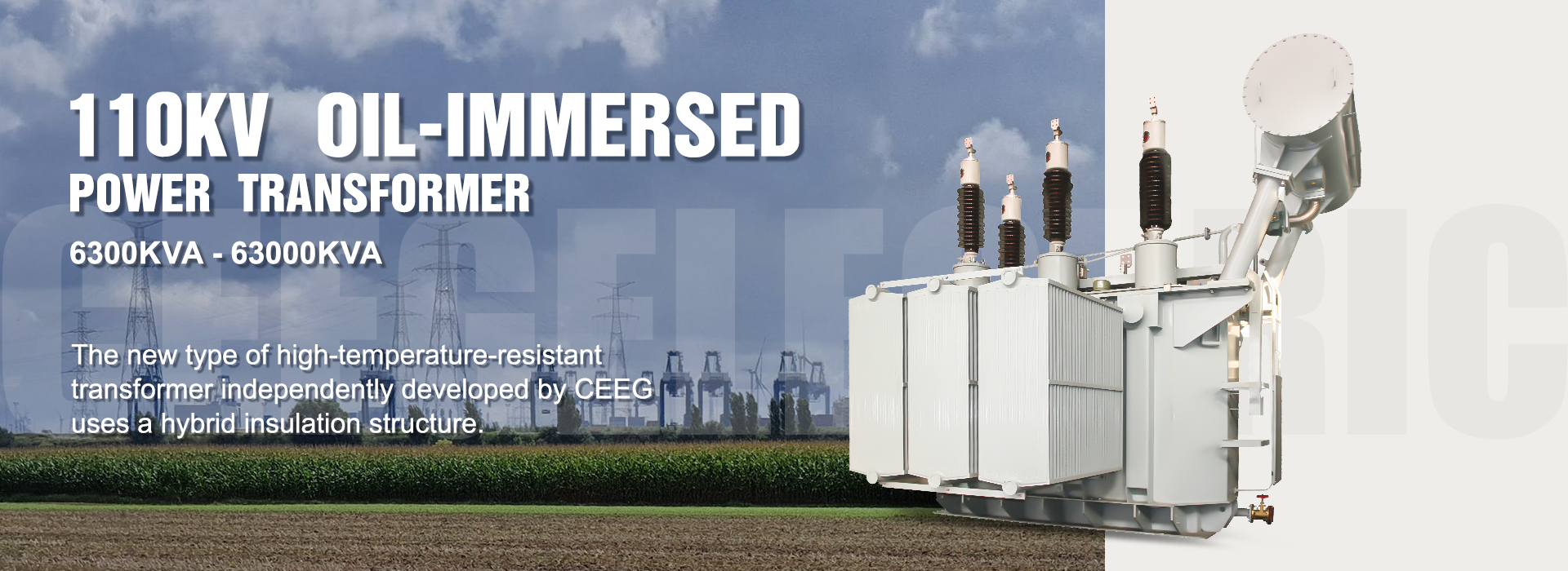
The 110kV power transformer finds wide applications in large and medium-sized urban power grids, major thermal power plants, rail transportation, new energy enterprises, coal, chemical industries, and other large industrial and mining enterprises.
Performance Features:
1. Utilizes advanced seven-level temperature control technology.
2. Low Losses: Adopts a special design scheme, reducing no-load losses by 20% compared to national standards and load losses by 5% below national standards.
3. Low Noise: Noise levels are 3 to 5 decibels lower than national standards.
4. Low Partial Discharge: Factory partial discharge is less than 100PC.
5. Leak-Free: All sealing components are made of acrylic one-time molded parts, and fluorescent, positive pressure, and negative pressure leak tests are conducted.
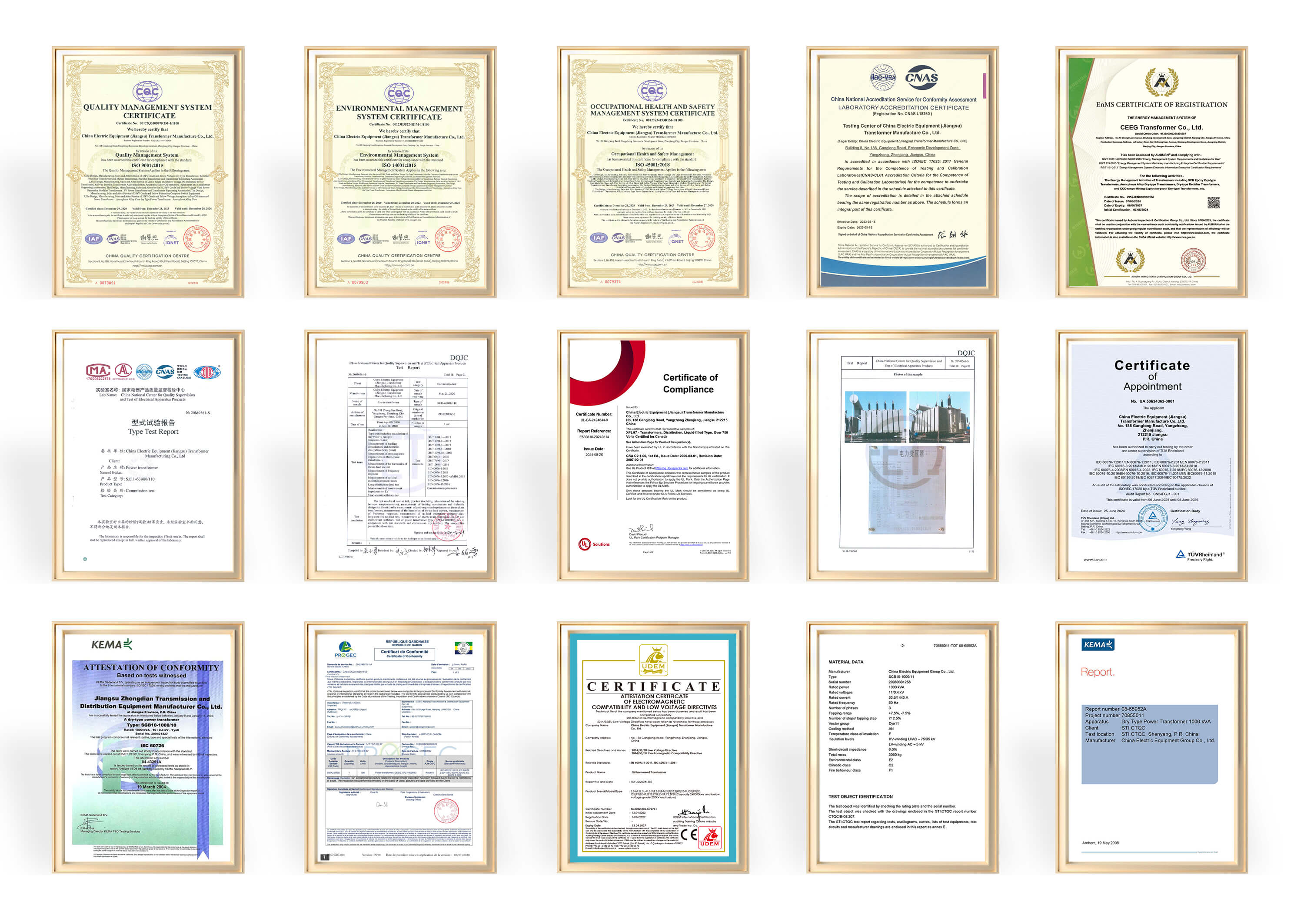
6. Short-Circuit Resistant: Successfully passes the sudden short-circuit test conducted by the National Transformer Testing Center.

Note:
1. For on-load tap changer transformers, step-down structure products are temporarily provided.
2. Negotiate with the manufacturer according to the user department products with other voltage combinations that can be provided, the maximum current tap is at -10% tap position.
Note:
1. step-down structure products are temporarily provided for on-load tap changer transformers.
2. The capacity distribution of high, medium, and low voltage windings is (100/100/100)%.
3. The label of the connection group can be YNd11y10 as required.
4. The maximum current tap is -10% tap position.
5. According to users' needs, the voltage value or taps different from those in the table can be selected for medium voltage.
Note: The maximum current tap is -5% tap position

 1. Reliability of Insulation Technology
Our research spans from initial two-dimensional electric field simulations, three-dimensional electric field measurements, and impact characteristic measurements to later-stage theoretical analysis and simulated experiments on the main insulation, longitudinal insulation, end insulation, insulation of leads, and coil withstand voltage characteristics of transformers. Through years of verification using various methods, we ensure the reliability of transformer insulation.
2. Calculation of leakage magnetic field and reduction of stray loss
Dedicate specialized efforts to calculating and measuring transformer leakage magnetic fields. The research includes shielding structures for leakage magnetic fields, calculations for transformer dynamics and thermal stability, and improvements in transformer dynamic and thermal stability to guarantee accurate calculations and reduce stray losses, enhancing transformer dynamic stability.
3. Precise Analysis of Coil Temperature Fields
Collaborating with numerous domestic universities, we jointly developed programs for calculating coil temperature fields. These programs calculate loss distribution in coils, including resistive losses, eddy current losses in different directions, and circulating losses between parallel conductors, as well as flow field cooling conditions. This enables the accurate calculation of coil temperature distribution and hotspot temperature rises, allowing us to take measures to control hotspot temperature effectively rises that impact transformer lifespan.
4. Reducing Local Discharge in Transformers
Electric field strengths at various locations have undergone numerical analysis during the design phase and have been strictly controlled. Additionally, compliance with manufacturing quality, the reliability of processing methods, and the reasonableness of operating techniques effectively control local discharges in transformers.
CEEG is a professional transformer manufacturer!